Jim Klinger, Concrete Construction Specialist, The VOICE Newsletter December 2023
Full Disclosure: Perhaps one of the most unwelcome telephone calls a concrete construction project manager could ever get usually comes first thing the Monday morning following a Friday foundation concrete placement that required setting of large anchor rod assemblies for follow-on steel buildings. Such phone calls always start with the general contractor (GC) saying that the steel erector's licensed surveyor has just completed his routine as-built location check and discovered a number of anchor rods are in the wrong place. The steel erector reports that all the project's steel column base plates have already been fabricated, welded to their respective columns, and loaded onto trucks awaiting imminent jobsite delivery. Furthermore, steel erection is scheduled to start in a week, and it now appears that these trucks will have to be unloaded so the affected column base plates can be taken back into the shop to be reworked. In some cases, the anchor rods appear to be so far out of place that the structural engineer is going to have to drop what he is doing and review each condition and advise on potential fixes. ("The engineer isn't in yet, but hey- we have a call in to his office", says the GC). The phone call continues with the GC advising that all handling, refabrication and all other associated costs will appear as back charges via a deductive change order to your subcontract as soon as all rework is complete, including any delay impacts to the steel erector or other trades affected by your field errors. Of course, the Owner's inspection agency must also perform unplanned steel fabrication shop inspections of the base plate rework, so those costs and any structural engineering fees will be rolled into your back charge as well.
The GC concludes the phone call with an engraved invitation to an emergency meeting with the Owner to be held this afternoon in the jobsite trailer at which your attendance is mandatory. "Be prepared to discuss the base plate rework, schedule impacts, impacts to other trades, and your proposed schedule recovery plans", says the GC.
The ASCC Hotline call depicted below represents a classic case where a simple--yet inconspicuous--detail was overlooked. Even with the best intentions and due diligence during the preconstruction and construction phases, sly little booby traps can sneak up and cost you money. In this case it turned out to be just a few man days to chip and patch the exposed bars. It could easily have been a lot worse.
______________________________________________________________________________
Question: We are constructing the reinforced concrete foundation, slab on grade and stub walls for a local elementary school project. The remainder of the building above grade is structural steel, with large-braced frames designed to meet seismic zone code requirements. The building perimeter (and most of the interior) spread footings feature anchor rod sets intended to connect large 3-inch-thick braced frame column base plates to the concrete foundation. At many locations, the steel base plates are 3 feet wide and 6 feet long.
We have worked on three previous projects with this same Owner, design team and GC; all of which have been successful for each stakeholder. The key to this success has been collaboration. Our field superintendents speak with the structural engineer on a weekly basis, and our project managers show up on site for every design team job walk. There is familiarity and mutual respect among the stakeholders.
ASCC Hotline callers know that ACI 117-10, section 1.1.3 specifies that a mandatory preconstruction tolerance coordination meeting be held among the various contractor stakeholders. Although contractor and material supplier attendance are mandatory, any design team and Owner attendance is optional. On our project, the structural engineer was happy to both attend and participate in the meeting. We reviewed the applicable ACI 117 tolerances for foundation concrete and ASCC Position Statement #14: Anchor Bolt Tolerances, which addresses anchor rod placement tolerances and oversized base plate holes that the steel fabricator will incorporate into the base plates on our project. The steel erector brought along a preview copy of the embed, anchor rod and column base plate shop drawings and distributed a hard copy to each meeting participant. Review comments were invited by the steel subcontractor before making a formal submittal.
During the preconstruction tolerance coordination meeting, the steel subcontractor advised that all parties should be aware of the as-built steel base plate thickness dimensions if we are going to base any of our layout line and grade using the nominal top of the steel base plate elevations shown on the construction documents as layout reference points. Because of the rather large size of the braced frame column base plates (and the project schedule), the top of each base plate will be milled at the fabrication shop, while the bottom of each base plate will be left with surfaces "as rolled" in the steel mill. In practice, this will result in base plates that could be slightly thicker than the nominal dimensions required by design. The steel detailers should show the as-built base plate thickness dimensions on the final set of shop drawings or erection drawings.
In our minds, the preconstruction tolerance meeting was cordial and productive. We walked away confident we had checked all possible due diligence boxes.
By and by, several pallets of 1-1/2 inch diameter anchor rods were delivered by the steel subcontractor FOB jobsite, along with setting templates made of steel plate; one template for each and every braced frame column was supplied. During the preconstruction conference, we discussed location checks conducted by licensed surveyors to verify the anchor rods were located correctly in plan and elevation. We hired a licensed surveyor to provide an initial layout and then check the anchor rod locations while the assemblies were first being tacked into place by our crew. As agreed (see below), the GC paid for the secondary survey check performed by the same licensed surveyor; conducted after all foundation reinforcing steel had been placed and inspected and after all anchor rods had been set. By the evening prior to pour day, all anchor rods had been surveyed and confirmed by licensed surveyors to be located correctly and secured, ready to receive concrete.
(N.B.: During the bid process, the GC proposed to the Owner that pre-pour anchor rod location survey checks be conducted on a cost-sharing basis. Since correct anchor rod placement is ultimately a critical path schedule activity, the GC felt it would be cheaper in the long run for the Owner to approve such an arrangement. Otherwise, we would have to carry a substantial general conditions line item to cover the risk and costs involved with potential field errors. The GC advised their thinking was that budgeting a few thousand dollars in up-front survey cost was a great insurance policy and schedule management strategy. All stakeholders and competing project bidders agreed; a Bulletin was issued by the Owner, and we all proceeded to price the job accordingly).
On concrete placement day, the pour went just like clockwork. The following day, the steel erector's licensed surveyor conducted their routine as-built survey and confirmed that each and every anchor rod set had been successfully cast in concrete, within ACI 117 tolerances, at the locations in plan and elevation indicated on the construction documents. But just when we started to take a victory lap, our field crew called in from the jobsite. We had overlooked a simple detail and made a concrete placement error that became apparent at almost every braced frame column location as soon as each template was stripped.
The problem? At each braced frame column location, the engineer designed a layer of #6 top bars in each footing that sit on the bottom layers of main footing reinforcement. These top bars are labeled "U-bars" in the schematic section cut through a typical column footing, see "Section A", below. (Old-school ASCC members probably call them "hat" bars). The actual footing main reinforcement, comprised of larger #11 bars, is not shown in the section for clarity (the schematic section is way out of scale, as well). When we stripped the templates away from each of the anchor rod sets, we could see straightaway that portions of the top U-bars did not get full concrete coverage and are partially exposed as shown in the photograph below. This condition occurs at almost every braced frame column footing location.
This is a school project located in a seismic zone, and the project inspector has already reported this (with photographs) to the Owner and GC, who have expressed concern. We don't believe this will cause a remove-and-replace scenario, but we are unsure how to proceed. Please advise how to propose a cost-effective repair plan, since we are now in danger of impacting the project schedule.
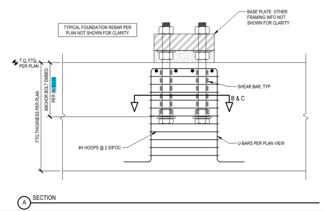
caption: schematic section cut through foundation, main reinforcement not shown.
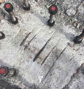
caption: exposed reinforcement after template has been removed.
Answer: We are familiar with the condition shown in the photograph. In this case, the bottom of each steel template was set to top of footing concrete elevation. When your field crew placed and vibrated the footing concrete, the photograph reveals that concrete never even got close to the bottom of the steel template. This predicament occurred because the template was fabricated as a solid sheet of steel with no provision for air to vent out (e.g. vent holes), or for your placing crew to visually confirm the concrete was placed to bottom of template (e.g. with "sight holes"). In other words, the concrete should have been placed right snug up against the bottom of each template, but it wasn't.
Interestingly enough, this particular condition is an unfortunate booby trap that is built into the system. In order to understand this, it is helpful to review what the ACI (American Concrete Institute) and AISC (American Institute of Steel Construction) requirements are for vent and sight holes in steel column base plates.
In the ACI Code (ACI 318-19) section titled "Anchoring to Concrete", section 26.7.1(e) requires the engineer to provide the following design information in the construction documents: "Size and location of base plate holes to permit inspection and vent air when placing concrete or grout per 17.11.1.2." (Section 17.11.1.2 apparently applies only to base plates fitted with shear lugs).
The following recommendation is given in AISC Design Guide 1, Base Plate and Anchor Rod Design, section 2.10: "Grout holes are not required for most base plates. For plates 24 in. or less in width, a form can be set up and the grout can be forced in from one side until it flows out the opposite side. When plates become larger or when shear lugs are used, it is recommended that one or two grout holes be provided. Grout holes are typically 2 to 3 in. in diameter and are typically thermally cut in the base plate".
So, it seems fair to say that whenever steel base plates are larger than 2 ft square, vent (or sight) holes should be provided. But nowhere in any industry documents does it imply or recommend that the corresponding templates for the base plates must be equipped with vent or sight holes to suit. This is what makes such a condition so easy to overlook during the preconstruction and construction (submittal) phases of a project.
By our inspection of the structural detail and the photograph taken at the jobsite, the most sensible and cost-effective repair is to simply define the area at the top of each footing featuring exposed reinforcement, enlarge each area say 6 inches all around (as measured from the outermost edge of the exposed bars), and chip down below the bottom of the exposed bars. Propose to restore each footing top to the correct dimensions and fully encase each bar using a commercial structural repair product. Chipping depth will depend on the manufacturer's printed installation instructions (MPII) and guidance from the reviewing engineer. As it turns out, the repair area will subsequently be completely covered with a protective grout layer when you place the follow-on grout underneath each column base plate.
(Note: It is our understanding that at the time of this writing, the repair procedure described above was submitted by the ASCC Hotline caller to the project licensed design professional (LDP), who has accepted the proposed repair. The concrete contractor was able to complete the repairs, stay ahead of the steel erector, and protect the project schedule).