Question: We are working on a City-funded seismic retrofit project designed to strengthen a large, existing (E) 7-story reinforced concrete mid-rise building. We understand the original structural concrete frame was cast sometime during the mid 1940's. Part of our contract scope includes installing full height reinforced concrete jackets that encase all existing (E) interior concrete columns and thickening the (E) concrete shear walls surrounding the vertical transportation (e.g. stair/elevator) core. Retrofit work--if any--at the foundation level or elevated CIP (cast-in-place) decks at the upper levels is not in our current contract scope. By design, all concrete column and wall retrofit jackets are specified to be cast in place using the shotcrete placement method.
The specified concrete surface preparation requirements for the new wall jackets include mechanical roughening of the entire (E) wall contact surface to a quarter-inch amplitude, chipping a grid network of beveled shear keys (2 inches wide, 6 inches long, and 1.5 inches deep nominal, each key), and installing drilled and epoxied, hooked dowels at 12 inches on center each way. One of the engineers told us the epoxy dowels were designed for shear transfer between the new jackets and the (E) concrete walls. In addition to shear transfer, each drilled dowel features 135-degree hooks; shown in drawing details capturing the jacket reinforcement curtains at vertical/horizontal bar intersections as well.
(N.B.: On background...Prior to bid time, our estimator attended a mandatory prebid conference/job walk hosted by the City and the Public Works design team. In addition to bidders representing the structural concrete and MEP trades (Mechanical, Electrical, Plumbing), representatives from several testing and inspection agencies looking to bid the job were in attendance as well. The licensed design professional (LDP) explained that the architect had scoured the City archives for information regarding the original building design and construction. As it turned out, the original architect, LDP and contractors of record were no longer in business. The architect's investigation included a visit to the resident building engineer's basement office to see if there was an old, rolled-up set of original blueprint drawings hiding somewhere; and several hours spent scrolling through microfiche archives at the City Public Works headquarters--all to no avail).
The structural portion of the architect's fact-finding effort included a visual condition survey conducted after the building had been cleared of its tenants. We were advised the design team investigators referred to ACI and ASTM protocols: for example, ACI 201.1R-08 Guide for Conducting a Visual Inspection of Concrete in Service and ASTM C823-12 Standard Practice for Examination and Sampling of Hardened Concrete in Constructions. Since the visual condition survey turned up no apparent signs of distress or serviceability issues in the as-built condition, destructive testing was deemed unnecessary (e.g. petrographic analysis, cores, and so on).
Using information learned at the prebid conference and supplemented in the project ITB (Instruction to Bidders), our estimator prepared a preliminary work schedule based on the following assumed five-step activity sequence:
- (1) Bush-hammer wall contact surface to the required amplitude;
- (2) Lay out and chip new shear keys;
- (3) Use pachometer to locate (E) outermost wall reinforcement;
- (4) Lay out grid of dowel holes to be drilled; and
- (5) Drill holes.
Since the depth of each drilled hole and each beveled key is measured relative to the adjacent concrete wall surface after roughening, our retrofit crew typically holds off on drilling until after the entire contact surface has been bush-hammered and all keyways have been chipped to their required depth.
During our initial roughening and shear key chipping operations (e.g. steps 1 and 2), the outside face of some outermost layer wall reinforcement was inadvertently exposed. This occurred either due to the bars being placed too close to the face of wall (e.g. insufficient concrete cover) in the original construction, or because the (E) rebar locations coincided with new key locations and were exposed when the keys were chipped.
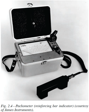
Our field crew even tried to use our company-owned, old-school pachometer (basically a glorified stud finder--married up with a land line telephone receiver--used to locate (E) reinforcing steel, noted above in step 3), but this turned out to be inconclusive. The idea, of course, is to calibrate the instrument, locate the (E) bars, and then plot their approximate location on a reasonably smooth concrete surface. We have had great success with this old instrument over the years, but in this case the concrete wall surface was too rough for us to determine rebar locations. We tried to do the pachometer work before scabbling the wall surface, but the readings were erratic, and any layout marks would get wiped out during the roughening process anyway.

Pachometer: reprint from ACI 224.1R-11.
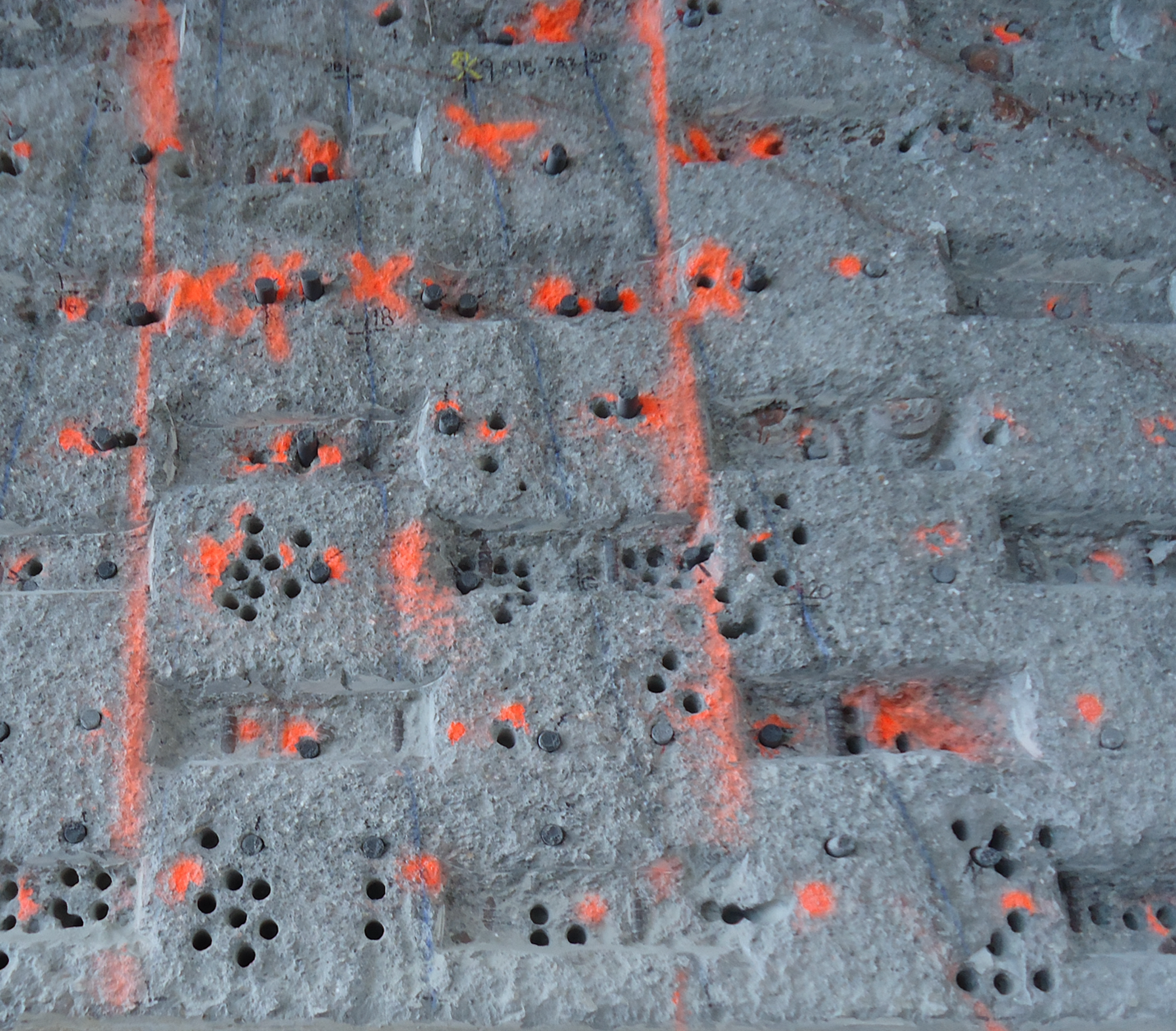
By the time our field crew finally began drilling the holes (step 5), they ended up hitting (E) reinforcing steel at every turn; with drill bit refusal occurring at various depths with no apparent rhyme or reason. What we ended up with is shown in the photograph below...a panoramic "Swiss cheese" mural of abandoned drilled holes (ADH).

Abandoned drilled holes (ADH) and shear keys at retrofit concrete wall.
After just a few hours of drilling, it dawned on us that the Swiss cheese scenario was going to be the rule--rather than the exception. On one hand, the City inspector was wondering how the field conditions might affect the specified "pull test" protocols established by the LDP. (The specifications called for the Owner's test agency to perform tension tests intended to proof load 10 percent of dowel production, each day.) We, on the other hand, were concerned because our installation labor costs were already running way over budget, not to mention the number of drill bits we were burning through.
At that point, we (including the City's full-time inspector) requested the LDP visit the jobsite for a job walk to observe the field conditions and provide guidance. After a brief meeting in the City onsite trailer, we convened at the wall to rinse out the issues. As it turned out, the LDP didn't seem bothered at all by what we showed him (see photo, above). In fact--just the opposite.
"This wall has been here for at least 80 years without even a crack", the LDP told us, "and it's not going anywhere now... the current ACI Code says we can't use drill and epoxy anchors until the parent concrete is 21 days old... obviously that's not an issue here. The retrofit is being driven by City ordinance coincident with a change in tenancy, not because of any structural distress...this concrete is here to stay, just ask your workers who are running the drills and chipping guns...just keep drilling, and try to get the holes as close as possible to their design location. Fill in all of the abandoned drilled holes (ADH) with either the approved non-shrink grout (drypack) or the approved epoxy adhesive...your choice...I will let you know if any pull test protocols need to be adjusted".
(N.B.: According to ACI 318-19-- Building Code Requirements for Structural Concrete--section 17.2.2 tells the LDP that "Adhesive anchors shall be installed in concrete having a minimum age of 21 days at time of anchor installation".)
Since the large number of ADH don't seem to be of structural concern, that still leaves the issue of the cost impacts, which we did not bring up during the job walk. At bid time, we estimated the number of holes required and multiplied that by our standard unit rate per each; a unit price we developed over the years and which does not consider ADH or cost of drypack or epoxy ADH infills. Neither we (nor the City inspector) have seen such a large number of ADH. We did not qualify our bid to say that we assumed a certain number of ADH and expect to be paid for anything beyond that. So far, we have kept a log of all time and materials expended so far, numbers which are recorded with City inspector oversight. How would you recommend we approach the City Council for an equitable reimbursement of our extra costs?
Answer: There are several interesting nuances at play here. Let's drill down just a little bit and learn what was driving the LDP's assessment.
First: We know from the prebid meeting that the design team made a good-faith effort to determine what the (E) reinforcement should have been, based on the 1940's-era construction documents. Unfortunately, such documents could not be located. A complicating factor is that the building was most likely built during--or just after--World War II. It is fair to say reinforced concrete construction at that time was highly dependent on what materials and labor force was readily available. The design may have called for unavailable bar sizes, and the equivalent area of reinforcement in smaller sizes was substituted instead. In other words, since they couldn't get the correct size bars, they used smaller bars--just a lot more of them. Short of demolishing the wall, there is no easy way to know what happened when the structure was being built.
Second: The LDP is obviously experienced with ADH, since he was able to review the work in the field and give guidance straightaway. At first glance, one might react the way you and the City inspector did, thinking this amount of ADH has got to be a structural problem. Here at the ASCC Hotline, we run into examples like this quite often where photographs indicate conditions that might initially appear unsavory, but upon further review it turns out that there really isn't a problem at all. So how did the LDP arrive at such a quick decision?
As is typical with the design and construction of reinforced concrete structures, almost everything engineers and concrete contractors do is based on testing, experience, and a healthy dose of engineering judgement. As it turns out, there have been several reports published that describe testing to determine the effects of abandoned drilled holes (ADH) on the load-carrying capacity of the survivors. In addition, some material suppliers have conducted/sponsored test programs on their own to understand how their products will perform under various ADH boundary conditions in the field.
We reviewed two such reports that appear in refereed engineering journals, and additional reports that were found in the adhesive (or anchor) manufacturer's web page technical sections. In a nutshell, the following general statements can be made about the load capacity of ADH:
- Typical drill bit refusal occurs at depths between 3/4 inch and 2 inches, which coincides with nominal concrete cover to reinforcing steel.
- As long as the ADH are backfilled with the appropriate drypack grout or adhesive material, the concrete will heal and never know what happened. In some cases, the load capacity might even be enhanced by backfilling.
- In general, if an ADH is 3 or more anchor diameters away from the successful hole, there is no effect on anchor capacity, even if the ADH is not backfilled.
- On the other hand, if the ADH is within 2 diameters of the successful hole and is not backfilled, the load capacity will be reduced.
The key takeaway here is to study the MPII (manufacturer's printed installation instructions), which will likely contain guidance on ADH relative to the product.
That information should then be worked with any drilled anchor details and specifications given by the LDP in your construction documents.
Third: In order to get paid for the extra time and materials in excess of what you estimated and priced at bid time, you will have to make the case that the (E) rebar locations could not fairly be determined, even after the work started. The only way, really, that rebar was located on your project was with a drill bit or a chipping gun. In other words, this is a case of unforeseen conditions. Since the City inspector concurs with your experiences, that should weigh heavily in your favor when your request for compensation is considered by the City Council. Since you have already developed a good rapport with the various City stakeholders, the good faith efforts demonstrated by all collaborators should go a long way in helping to make your case.
___________________________________________________________________
Question: What do we do when tolerances for a work item do not appear in the construction documents? If the tolerance value is not specifically stated, doesn't that automatically mean that the tolerance is zero?
Answer: In order to answer this one, we can find guidance in two important specifications published by ACI, namely ACI 117-10 Specification for Tolerances for Concrete Construction and Materials, and ACI 301-20 Specifications for Concrete Construction. In both cases, the body of the specification text does not specify certain default tolerances for some items. When that happens, the specification writer must use the checklists--given at the back of both ACI documents--titled "Mandatory Requirements Checklist" before releasing the project out for bid. In both cases, the designer has to do his homework and supply certain tolerances in the construction documents if they are really that important and desired by the Owner. If the specification preparer does not follow through with this task, then there is no contractor tolerance requirement. This does not automatically mean that the tolerance is zero.
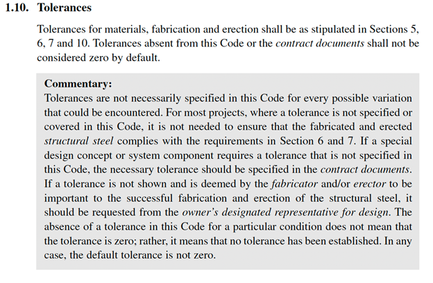
We can also "check the other guy's playbook" and view this condition through the lens of our structural steel colleagues. In this case, the playbook is the AISC (American Institute of Steel Construction) Code of Standard Practice for Steel Buildings and Bridges (2016), section 1.10 Tolerances, as follows below:

___________________________________________________________________
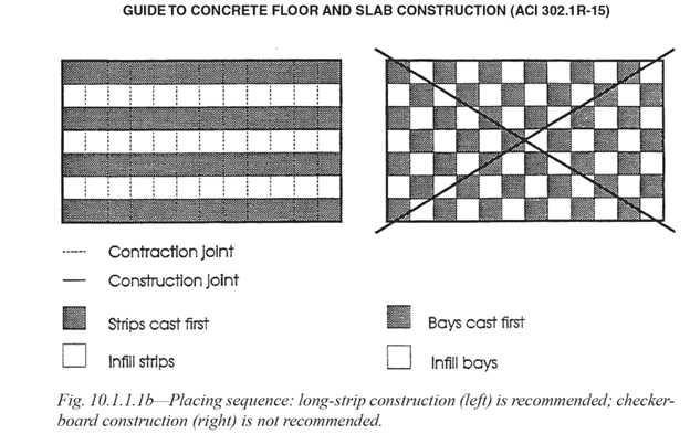
Question: We are working on a large, commercial "big box" project that features a building footprint of approximately 200,000 GSF (gross square feet). At bid time, our estimators divided the footprint into six equal sized slab-on-grade pour placements as shown in the plan view, below. This plan is excerpted from the submittal we prepared intended to show construction joint locations only. Once approved, we intended to distribute the plan to all of the follow-on trades for their use in planning their scopes relative to ours. Separate drawings were submitted that showed reinforcement placing and saw cut joint locations.

We were surprised when the design team rejected our pour plan, claiming that our layout constitutes a so-called "checkerboard pattern", which we all know has been frowned on by ACI for many years now.
We are looking to the ASCC Hotline to provide guidance. Please advise.
Answer: The plan you submitted features placements with aspect ratios that are clearly not arranged in "checkerboard" fashion. In fact, just the opposite. Below is an excerpt from ACI 302.1R-15 Guide to Concrete Floor and Slab Construction which straightaway tells the story at first glance. As you can see in Fig. 10.1.1.1b below, your plan is clearly a variation on the "long-strip" construction placing sequence configuration and nowhere close to looking like a checkerboard. Getting the design team's decision reversed should be a fairly straightforward matter.

___________________________________________________________________
Question: We are one of three competitors in the hunt for a project that bids this coming fall. The project is a three-building apartment complex featuring reinforced concrete podium-type structural frames. Each frame includes 2 levels of parking below grade, and wood "stick" apartment framing starting at each podium level. We--and our competitors--have been providing budget estimates over the past year. All three of us have built for this private developer in the past, although not with the same GC (general contractor). This Owner likes to spread the work around.
After each round of budgeting, we make it a point to call the GC a week or so later to ask how our number is looking. (Sometimes we can get a "whisper number", but in this case--no dice). The best we can get is the encouraging reveal disclosure that our price is "competitive".
Throughout the budgeting process, the LDP has shown most (but not all) walls as cast in place, using the shotcrete method of placement. A fair amount of walls at the parking levels, however, are shown as CMU (concrete masonry units). From what we can tell from the CMU typical details and the span lengths shown on the floor plans, these CMU walls must be load bearing, which means they have to be installed by others--and grouted--before the supported slabs in our scope are placed. In fact, it may be entirely possible that we will not even be able to erect our scaffold shores until the block subcontractor has demobilized.
Based on successful past experience, we are confident we can shave time off the schedule and save the Owner money by requesting a substitution to get the CMU walls changed to shotcrete. We intend to include the substitution as a VE (value engineering) alternate at the end of our bid proposal letter. Customarily--and most likely contractually-- "Request for Substitution" (aka RFS) proposals must be crafted with a narrative that explains how the proposed substitution will benefit the Owner in terms of Quality, time, and dollars.
At one of our recent weekly, in-house estimator's meetings with our project managers and our company ownership, we penciled out the possible cost and schedule scenarios if the CMU walls were changed to concrete and added to our scope. How many shoot days would we now need? How much backforming would we have to pick up? How much rebar would have to be installed, and at what scheduled time frame? And then the kicker: when we submit our formal substitution request, what quality of surface finish will we advertise? What "or equal" tolerances should we say we will follow for the substituted shotcrete walls?
At this stage of the game, the construction documents are silent regarding tolerances for the shotcrete walls that are already shown on the drawings, let alone for any work added after the fact. In addition (and sorry to say), none of our own team members working on the estimate even considered shotcrete tolerances during the budgeting process as well.
What tolerances should we follow for the shotcrete work already shown in the construction documents, and what tolerances should we propose to build to if the CMU-to-shotcrete RFS is accepted? Please advise.
Answer: In order to rinse this one out, we need to review certain ACI document requirements that apply to shotcrete tolerances--in step-by-step fashion--as follows below:
- ACI 117-10 section 1.1.2 tells designers and contractors that the document scope does not include tolerances for shotcrete.
- ACI 301-20 section 1.1.5 tells the contractor "Use shotcrete as designated in Contract Documents".
- ACI 301-20 Mandatory Requirements Checklist item 1.1.5 tells the specifier to "Designate portions of Work to be constructed of shotcrete. Concrete sections not initially designated as shotcrete may be subsequently considered for shotcrete placement after Contractor submittal for consideration. Refer to ACI 506R for guidance on shotcrete. Review ACI 506.2 and ACI 318 and specify requirements for shotcrete..."
- ACI 506.2-13 Specification for Shotcrete section 3.8.1 tells designers and contractors "Dimensional tolerances of shotcrete shall comply with Contract Documents".
- ACI 506.2-13 Mandatory Requirements Checklist item 3.8.1 tells the specifier "Specify tolerances based on function and appearance. Shotcrete can be built to the same tolerances as cast-in-place concrete; however, for some structures such as tunnels, only cover thickness is required and tolerances are not specified unless project-specific requirements dictate. Sometimes shotcrete tolerances are increased by a factor of 2 from those in ACI 117..."
- ACI 506R-16 Guide to Shotcrete section 3.8 Tolerances: tells the reader "...shotcrete structures can be built to the same degree of accuracy and tolerance as cast-in-place concrete".
Considering the above in its entirety, we can say the following:
- The LDP is obviously familiar with and comfortable with the shotcrete method of concrete placement. This will be helpful when it comes time for the LDP to review nozzleman's qualification cores and the actual contract work.
- The ACI 301 and ACI 506-series documents were written with the above in mind. Based on Mandatory Requirement checklist item 3.8.1 that appears in ACI 506.2-13, the LDP is obligated to approach each project in common sense fashion. In other words, the LDP has to sit down, think about the upcoming project at hand, and then create the construction documents--including appropriate tolerances--to suit.
- Since you are still working with in-progress budget documents--roughly Level 4, or 75 percent complete (see ASCC VOICE Guidance column #3, Jan. 2022, for more on estimate levels), it is not surprising that the LDP has not yet specified the tolerances appropriate for the project. On the previous project that you shot with this LDP, what tolerances were specified? Did the question even come up?
- We suggest you review the architectural documents to determine if any of the concrete walls are likely to be designated "architectural concrete". For the CMU walls, check the finish schedule to see if any of those will be covered with a follow-on "architectural" finish. This will give you an idea of the likely backform tolerances you will need to meet in order to satisfy Owner Quality expectations if the switch is made from CMU to shotcrete.
- Take a look at the other guy's playbook. In this case, said playbook includes the Division 4 Masonry specification sections. If the CMU is changed to concrete, is there anything hiding in the Div. 4 playbook that you will inherit?
- ACI 301-20 Mandatory Requirement checklist item 1.1.5 recognizes that the concrete contractor might propose to build the work using the shotcrete placement method. If the VE change is accepted, some jurisdictions (e.g. public works projects) might require a formal revision to the specifications and the design drawings to incorporate the change from CMU to shotcrete. In that case, you are likely to have to cover the cost of the "redesign". It sounds like on this project, such engineering fee "backcharge" may be waived. At least be aware of this potential cost associated with material change when you are estimating your VE cost items.
- Depending on the way the Owner's test agency contract is crafted, there may be "extra" testing and inspection costs associated with the substitution from CMU to concrete. Example: the inspection and testing required for the shotcrete nozzleman's qualification and so on versus the cost of inspecting and testing masonry prisms, etc.
(N.B.: On some projects (not this one), reinforced concrete walls indicated as "form-and-pour" may be changed to shotcrete at contractor request. LDP "redesign" costs would not be appropriate in this case, since there is no revised structural design, only a change in the means and methods of forming and placement).
_____________________________________________________________